| XC3000 | XC4000E | XC4000X | XC5200 | XC9000 | Spartan | SpartanXL | Virtex |
|---|---|---|---|---|---|---|---|
| N/A | N/A | N/A | N/A | Macro | N/A | N/A | N/A |

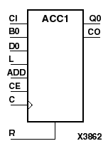
ACC1 can add or subtract a 1-bit unsigned-binary word to or from the contents of a 1-bit data register and store the results in the register. The register can be loaded with a 1-bit word. The synchronous reset (R) has priority over all other inputs and, when High, causes the output to go to logic level zero during the Low-to-High clock (C) transition. Clock (C) transitions are ignored when clock enable (CE) is Low.
The accumulator is asynchronously cleared, outputs Low, when power is applied. For CPLDs the power-on condition can be simulated by applying a High-level pulse on the PRLD global net.
When the load input (L) is High, CE is ignored and the data on the input D0 is loaded into the 1-bit register during the Low-to-High clock (C) transition.
When control inputs ADD and CE are both High, the accumulator adds a 1-bit word (B0) and carry-in (CI) to the contents of the 1-bit register. The result is stored in the register and appears on output Q0 during the Low-to-High clock transition. The carry-out (CO) is not registered synchronously with the data output. CO always reflects the accumulation of input B0 and the contents of the register, which allows cascading of ACC1s by connecting CO of one stage to CI of the next stage. In add mode, CO acts as a carry-out, and CO and CI are active-High.
When ADD is Low and CE is High, the 1-bit word B0 and CI are subtracted from the contents of the register. The result is stored in the register and appears on output Q0 during the Low-to-High clock transition. The carry-out (CO) is not registered synchronously with the data output. CO always reflects the accumulation of input B0 and the contents of the register, which allows cascading of ACC1s by connecting CO of one stage to CI of the next stage. In subtract mode, CO acts as a borrow, and CO and CI are active-Low.
Figure 3.1 ACC1 Implementation XC9000 |