| XC3000 | XC4000E | XC4000X | XC5200 | XC9000 | Spartan | SpartanXL | Virtex |
|---|---|---|---|---|---|---|---|
| N/A | Macro | Macro | Macro | N/A | Macro | Macro | N/A |

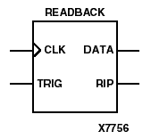
The READBACK macro accesses the bitstream readback function. A Low-to-High transition on the TRIG input initiates the readback process. The readback data appears on the DATA output. The RIP (readback-in-progress) output remains High during the readback process. If you use the ReadAbort:Enable option in BitGen, a High-to-Low transition on the TRIG input aborts the process. The signal on the CLK input clocks out the readback data; if no signal is connected to the CLK input, the internal CCLK is used. Set the ReadClk option in BitGen to indicate the readback clock source.
Typically, READBACK inputs are sourced by device-external input pins and outputs drive device-external output pins. If you want external input and output pins, connect READBACK pins through IBUFs or OBUFs to pads, as with any I/O device. However, you can connect READBACK pins to device-internal logic instead. For details on the READBACK process for each architecture, refer to The Programmable Logic Data Book.
Virtex provides the readback function through dedicated configuration port instructions, instead of with a READBACK component as in other FPGA architectures. Refer to the “CAPTURE_VIRTEX” section for information on capturing register (flip-flop and latch) information for the Virtex readback function.
Figure 9.9 READBACK Implementation XC4000, XC5200, Spartans |