|
|
|
|
|
|
| XC3000 | XC4000E | XC4000X | XC5200 | XC9000 | Spartan | SpartanXL | Spartan2 | Virtex |
|---|---|---|---|---|---|---|---|---|
| N/A | N/A | N/A | N/A | Macro | N/A | N/A | N/A | N/A |
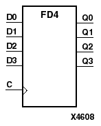
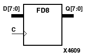
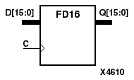
FD4, FD8, FD16 are multiple D-type flip-flops with data inputs (D) and data outputs (Q). FD4, FD8, and FD16 are, respectively, 4-bit, 8-bit, and 16-bit registers, each with a common clock (C). The data on the D inputs is loaded into the flip-flop during the Low-to-High clock (C) transition.
The flip-flop is asynchronously cleared, output Low, when power is applied. For CPLDs, the power-on condition can be simulated by applying a High-level pulse on the PRLD global net.
| Inputs | Outputs | |
|---|---|---|
| Dz - D0 | C | Qz - Q0 |
| 0 | 0 | |
| 1 | 1 | |
| z = 3 for FD4; z = 7 for FD8; z = 15 for FD16 | ||