| Element | XC3000 | XC4000E | XC4000X | XC5200 | XC9000 | Spartan | SpartanXL | Virtex |
|---|---|---|---|---|---|---|---|---|
| ILDX | N/A | Macro | Macro | N/A | N/A | Macro | Macro | Macro |
| ILDX4, ILDX8, ILDX16 | N/A | Macro | Macro | N/A | N/A | Macro | Macro | Macro |


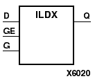
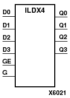
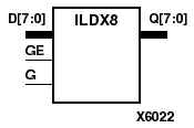
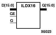
ILDX, ILDX4, ILDX8, and ILDX16 are single or multiple transparent data latches, which can be used to hold transient data entering a chip. The latch input (D) is connected to an IPAD or an IOPAD (without using an IBUF). When the gate input (G) is High, data on the inputs (D) appears on the outputs (Q). Data on the D inputs during the High-to-Low G transition is stored in the latch.
The latch is asynchronously cleared, output Low, when power is applied. FPGAs simulate power-on when global set/reset (GSR) is active. GSR (XC4000, Spartans) default to active-High but can be inverted by adding an inverter in front of the GSR input of the STARTUP symbol.
The ILDX is actually the input flip-flop master latch. Two different outputs can be accessed from the input flip-flop: one that responds to the level of the clock signal and another that responds to an edge of the clock signal. When using both outputs from the same input flip-flop, a transparent High latch (ILDX) corresponds to a falling edge-triggered flip-flop (IFDX_1). Similarly, a transparent Low latch (ILDX_1) corresponds to a rising edge-triggered flip-flop (IFDX).
Refer to the following figure for legal IFDX, IFDX_1, ILDX, and ILDX_1 combinations.
Figure 6.35 Legal Combinations of IFDX and ILDX for a Single IOB in XC4000 and Spartans |
| Inputs | Outputs | ||
|---|---|---|---|
| GE | G | D | Q |
| 0 | X | X | No Chg |
| 1 | 0 | X | No Chg |
| 1 | 1 | 1 | 1 |
| 1 | 1 | 0 | 0 |
| 1 | D | d | |
| d = state of input one setup time prior to High-to-Low gate transition | |||
Figure 6.36 ILDX Implementation XC4000, Spartans |
Figure 6.37 ILDX Implementation Virtex |
Figure 6.38 ILDX8 Implementation XC4000, Spartans, Virtex |