Hierarchical Schematic Designs
A design has a hierarchical structure if any of the symbols on the schematic sheet contain an underlying netlist or schematic. The hierarchical macros may be user-created or may already exist in a library. If you use one of these symbols, your design becomes hierarchical.
Creating a Schematic Macro (Bottom-Up Methodology)
To create a schematic macro using a bottom-up methodology, perform the following steps.
- Before you start drawing a schematic, make sure that the necessary libraries have been assigned to the project. You can view the currently attached project libraries in the Files tab of the Project Manager.
- To add additional libraries, select File
 Project Libraries from the Project Manager.
- When the Project Libraries window displays, select the appropriate libraries and then press Add.
This operation transfers the selected libraries from the Attached libraries window to the Project Libraries window, which makes these libraries available to Schematic Capture.
- Enter your schematic design in Schematic Capture, just like any other flat design, with the following constraints:
- Each macro is a self-enclosed entity. Any connection to the top-level sheet can only be performed through hierarchy connectors.
- The hierarchy connectors must be specified explicitly as Input, Output, or Bidirectional. This specification is important because the design entry tools automatically generate a symbol. The location of the pins on the symbol depends upon their schematic I/O definition (only inputs are on the left-side of the symbol outline). If needed, edit this symbol in the Symbol Editor.
- To create the macro symbol, select Hierarchy
 Create Macro Symbol from Current Sheet from the Schematic Capture window. The new symbol is automatically placed in the current project's working library.
Recognizing Hierarchical Macros
You can recognize hierarchical macro symbols by their color. By default, the schematic-based macros are dark blue. The netlist-based macros are purple. You can change these default colors by selecting View  Preferences
  Colors.
Navigating the Project Hierarchy
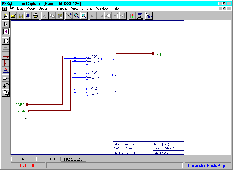
You can view the schematic of a hierarchical symbol by selecting Hierarchy  Push. When the H cursor is active, double click on a symbol to display its underlying schematic. You can use the tabs at the bottom of the Schematic Capture window to navigate between the top schematic (CALC in the following example) and its opened macro schematics (CONTROL and MUXBLK2A in the following example).

If you double click on a symbol that does not have an underlying schematic, HDL, or FSM file, the following message displays:
Symbol is a primitive cell.
To exit the H cursor mode, select Hierarchy  Pop.
Pop.
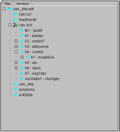
You can also navigate the hierarchical structure of the design from the Files tab on the Project Manager window shown in the next figure.

Hierarchy sublevels can be expanded or collapsed by double-clicking on the + or - icons.
The Hierarchical Browser window shows the hierarchical design tree. A plus (+) designates a hierarchy with additional hierarchical sublevels. You can open them by double clicking on these icons.
A minus (-) denotes a hierarchy that already shows lower hierarchy levels. Double clicking on the - symbols inside the icons reduces the hierarchy to the higher levels, which simplifies the viewing of very complex designs.
An icon with no symbol indicates that the given hierarchical level has no additional hierarchical sheets.
NOTEDouble clicking on the top schematic name or the name of any of its underlying schematic macros loads that schematic to the screen for viewing and editing.
|
Modifying Existing Macros
If you want to make some changes to an existing macro schematic, perform the following steps:
- Push into the schematic macro by clicking the Hierarchy Push/Pop icon and double clicking on the macro symbol.

- Select the Select and Drag toolbar button to enter edit mode.

- Make changes to the schematic.
- Select File
 Save.
Save.
When you change and save a hierarchical macro, you change all instances of this macro in the entire design. If the modified macro schematic has different I/O pins, its symbol changes and the pins may not match their previous locations on the schematics. If this happens, the wrong wires are automatically disconnected and will be marked with crossed circles. These wires must be manually reconnected by dragging the crossed circles over the target pins and then releasing the mouse button.
If you edit a macro from the system library that comes with the product, you cannot save it in the system library. You can only save it into a project library. For clarity, use a different name for the modified macro so that you can always be sure which symbols are currently used on the schematics.
Difference between a Macro and a Schematic
The following example explains what happens with the hierarchical schematic when you create a macro. Assume that the project TEST contains the schematic sheets TEST1 and TEST2. Create a macro for the schematic sheet TEST2 as follows:
- Using the Hierarchy
 Create Macro Symbol From Current Sheet option, convert the TEST2 schematic into a macro called MACRO1 in the TEST project library.
The old schematic sheet TEST2 still resides in the project directory. You can open this schematic file, but there is no longer any relationship between the TEST2.SCH schematic file and the TEST project or MACRO1.
- Use the Windows Explorer to delete the file TEST2.SCH from the project directory.
Hierarchy Symbol Changes
If you update a hierarchical macro, its symbol is not modified unless I/O pins change. When pin change, a new symbol is generated based on the new I/O pins, which may result in incorrect connections on the schematics that have previously used the symbol. The schematics that are currently open are automatically updated with the new symbol when you make the change. Other schematics are updated when you open them in the Schematic Editor.
When the symbols do not match the previous connections, the wires are automatically disconnected from that symbol, and a crossed circle is displayed at the end of these wires. To correct these connections, you can drag the circles and drop them at the appropriate pins.
You can edit the newly created symbol in the Symbol Editor program so that it matches the old pin locations.
Using a Top-down Methodology
To implement a top-down design, you first create a symbol for the hierarchical macro and then create the underlying schematic.
- To create an empty symbol, select the Hierarchy
 New Symbol Wizard from Schematic Capture.
- Click Next.
- In the Design Wizard - Contents dialog box, choose Schematic in the Contents section. Enter the Symbol Name and then select Next.
- In the Design Wizard - Ports dialog box, select New.
- Enter all ports including bus pins and power supply pins, if any. Select Next.
- In the Design Wizard - Attributes, enter a reference for the new symbol. Select Next.
- Click Finish in the Design Wizard - Contents window.
- Place the symbol on a schematic sheet and make the required connections.
- Push down into the symbol by clicking the Hierarchy Push/Pop function and double clicking on the macro symbol.

An empty schematic sheet appears with the selected symbols' input pins located to the left and the output pins located to the right.
- Enter the design and then select File
 Save.
Save.
Hierarchical Design Example
This example explains how to create and use a hierarchical design.
- Create a new project called MACROS.
- From the Project Manager, select File
 New Project.
- In the Name field of the New Project window, enter MACROS and click OK.
- Create the MACROS1 schematic.
- Click the Schematic Capture icon on the Design Entry button.
- Select the Symbol mode in the schematic toolbar and in the SC Symbols toolbox, select the NAND2 symbol.
- Draw the schematic shown in the “MACROS1 Schematic” figure including the input terminals, (INA, INB, INC) and output terminal (OUT).
- Use the Hierarchy Connector icon (shown below) to draw the input and output terminals. Make sure you add the input and output buffers.

- Connect the symbols (Mode
 Draw Wires).
You can edit symbol dimensions and pins using the Symbol Editor. To open the Symbol Editor, select Options  Symbol Editor from Schematic Capture, or double click on the placed symbol, and click the Symbol Editor button on the Symbol Properties dialog box. For more information on using the Symbol Editor, refer to the Symbol Editor's online help (Help
  Contents).
- Save the schematic using File
 Save. The schematic is automatically named as MACROS1.
- Create the MACROS1 symbol.
- Select Hierarchy
 Create Macro Symbol From Current Sheet. The Create Symbol window should display the symbol name MACROS1. Click on that name and change it to ONE, which will be the name of the hierarchical macro symbol. In the Input pins section, make sure that the following list of pins is entered: INA, INB, INC. Ensure that OUT is entered in the Output field.
- Click OK. The netlist and the MACROS1 schematic are saved in the project library and a graphical symbol is automatically created. A verification message displays to allow you to edit the macro, if necessary, before continuing. Click No.

- Create the second schematic (MACROS2).
- Select File
 New Sheet. A new schematic MACROS2 is automatically opened.
- Select the Symbol mode in the schematic toolbar. In the SC Symbols toolbox, select the FD symbol.
- Draw the schematic shown in the “MACROS2 Schematic” figure including the input terminals (D, CLK) and output terminal (OUT). Use the I/O Terminal icon to draw the terminals. Make sure you add the input and output buffers.
- Connect the symbols (Mode
 Draw Wires).
You can edit symbol dimensions and pins using the Symbol Editor. To open the Symbol Editor, select Options  Symbol Editor from the Schematic Editor, or double click on the placed symbol, and click the Symbol Editor button on the Symbol Properties dialog box. For more information on using the Symbol Editor, refer to the Symbol Editor's online help (Help
  Contents).
- Save the schematic using File
 Save. The schematic is automatically named as MACROS2.
- Create the MACROS2 symbol.
- Select Hierarchy
 Create Macro Symbol From Current Sheet. The Create Symbol window should display the symbol name MACROS2. Click on that name and change it to TWO, which will be the name of the hierarchical macro symbol. In the Input pins section, enter pins: CLK, D. Enter OUT in the Output field. Note that only I/O terminals are recognized as pins for the symbol.
- Click OK. The netlist and the MACROS2 schematic are saved in the project library and a graphical symbol is automatically created.
- Save the schematic using the Save option.
- Create a new sheet for the top level.
- Select File
 New Sheet. The empty sheet called MACROS3 opens.
- Select Mode
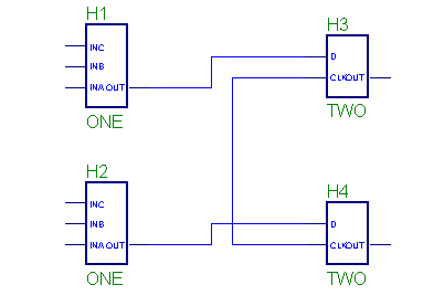
 Symbols and find symbol ONE in the SC Symbols toolbox. Place two copies of that symbol, which are automatically called H1 and H2, on the schematic. Similarly, place two copies of the TWO symbol on the schematic. These symbols are automatically named H3 and H4. Refer to the following figure for placement details.

- Use the Push/Pop option to view schematics.
Select Hierarchy  Hierarchy Push. A cursor with the letter H displays. Point the cursor at the Symbol H1 and double click the mouse button. The schematic ONE opens showing you the schematic of the symbol H1.
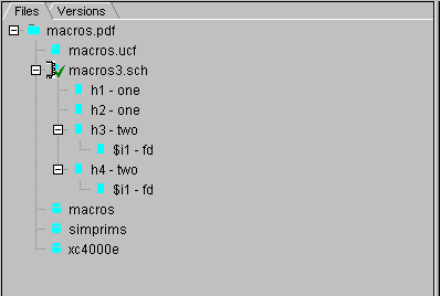
- View the project contents in the Files tab (shown in the following figure) of the Project Manager.


![]() Preferences
Preferences ![]() Colors.
Colors.![]() Push. When the H cursor is active, double click on a symbol to display its underlying schematic. You can use the tabs at the bottom of the Schematic Capture window to navigate between the top schematic (CALC in the following example) and its opened macro schematics (CONTROL and MUXBLK2A in the following example).
Push. When the H cursor is active, double click on a symbol to display its underlying schematic. You can use the tabs at the bottom of the Schematic Capture window to navigate between the top schematic (CALC in the following example) and its opened macro schematics (CONTROL and MUXBLK2A in the following example).
![]() Pop.
Pop.


