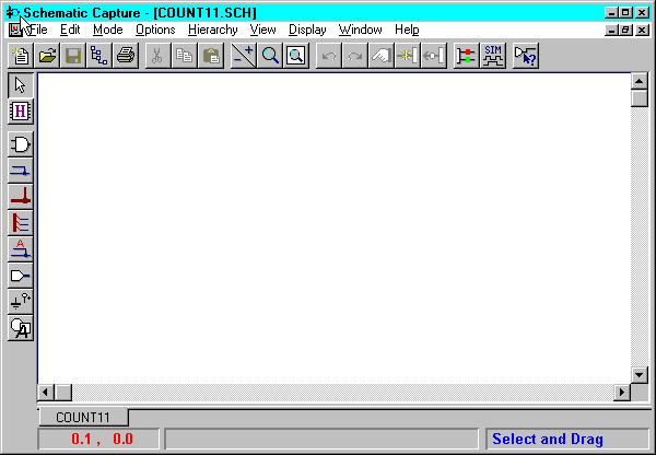
The following subsections describe various features of the schematic design tool.


You can create Foundation schematic editor designs that have the following structures:
Selecting a structure depends on the design size (number of symbols and connections), purpose (board or chip design), and company standards. The following sections describe each of these design types.
Single sheet designs are typically used for small designs. The largest page size is 44” x 34” (size E). The major advantage of a single sheet schematic is that you can use physical connections for an entire design, which makes tracking of the connections easier.
The disadvantages of using large pages are:
If a design is too large to print on a single sheet, you can use a multi-sheet design structure. When you create a new sheet, it is automatically added to the current project. To make connections between schematic sheets, you must make logical connections by using the same net names. For example, if you use the net CLOCK on sheet 1 and net name CLOCK on sheet 2, then both net segments are logically connected.
These connections can be confirmed by using the Query option. To activate the Query option, select Mode ![]() Query from the Schematic Capture main window and then select items on the schematic. To find out more about Query options, select Help
Query from the Schematic Capture main window and then select items on the schematic. To find out more about Query options, select Help ![]() Schematic Editor Help Contents from the Schematic Capture main window. Select the Index tab. Type Query in the search list box. Double click querying connections.
Schematic Editor Help Contents from the Schematic Capture main window. Select the Index tab. Type Query in the search list box. Double click querying connections.
Following are the advantages of using the multi-sheet design structure.
All reference designators for symbols in the multi-sheet schematics must be unique. The Foundation design entry tools automatically assign these unique numbers. If you manually assign the same reference numbers to two different devices, an error is reported when you create a netlist.
Since large number of symbols are used in FPGA and CPLD designs, handling large designs using the multi-sheet design structure can become very difficult and complex. Large designs typically require thousands of simple primitives like gates and flip-flops. To simplify schematics, designers prefer to use high-level components that have clear functionality. These high-level components are implemented using hierarchical macros. A hierarchical macro, a device in the library that looks like a standard component, is implemented as a symbol with an underlying schematic or netlist. For example, you can create an equivalent of a counter by drawing a macro schematic with only gates and flip-flops. This macro can then be saved and reused in your designs. All FPGA and CPLD libraries already contain many hierarchical macros.
Hierarchical designs are very effective with IC designs. In hierarchical macro schematics, all net names and reference names are local, which means that you can use the same signal names in different macros.
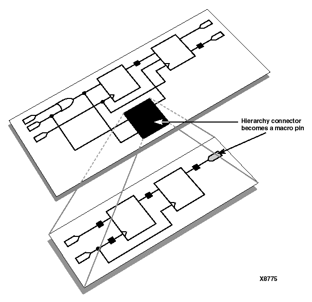
The connections between hierarchical macro symbols and the underlying schematic is made via hierarchy connectors. Use the Hierarchy Connector icon (shown below) in the Schematic Capture toolbar to place hierarchy connectors.

These connectors are converted into hierarchical symbol pins as illustrated in the following figure.

After the macro symbol is placed on the schematic sheet, you can connect wires to these pins on the macro. Only the signals shown as symbol pins can be connected.
Some advantages of hierarchical designs follow:
Following are some of the disadvantages of hierarchical designs:
To create a new empty sheet, select File ![]() New Sheet. The new sheet receives the name of the project with the sequential sheet number assigned to it automatically. You can save the sheet with a different name by selecting File
New Sheet. The new sheet receives the name of the project with the sequential sheet number assigned to it automatically. You can save the sheet with a different name by selecting File ![]() Save As. Each new sheet is automatically added to the project contents in the Hierarchy Browser. All schematic sheets that have been added to the project are visible in the Files tab of the Hierarchy Browser.
Save As. Each new sheet is automatically added to the project contents in the Hierarchy Browser. All schematic sheets that have been added to the project are visible in the Files tab of the Hierarchy Browser.
To open a sheet that does not belong to the project, select File ![]() Scratchpad. To add a scratchpad sheet to the project, use the File
Scratchpad. To add a scratchpad sheet to the project, use the File ![]() Save As option to define the schematic name. Then select Hierarchy
Save As option to define the schematic name. Then select Hierarchy ![]() Add Current Sheet to Project.
Add Current Sheet to Project.
To add an existing schematic sheet to your project, select Hierarchy ![]() Add Sheets to Project. In the Add to Project window, select the schematic file(s) you want to add and click the Add button. The schematic editor loads each added sheet and verifies that the symbols used in these schematics are available and that there are no duplicate reference numbers. The list of project sheets is then updated.
Add Sheets to Project. In the Add to Project window, select the schematic file(s) you want to add and click the Add button. The schematic editor loads each added sheet and verifies that the symbols used in these schematics are available and that there are no duplicate reference numbers. The list of project sheets is then updated.
The schematic editor automatically adds libraries used by its schematic sheets to the current project even if they are not listed in the project libraries. The libraries are added when you open a schematic file and symbols are not found in the current project libraries.
When you select File ![]() Open, only the sheets that belong to the current project are shown. If you want to open a sheet that does not belong to the current project, use the Browse button to select a schematic file from any disk. The schematics opened with the Browse option display the Cannot Edit message in their title bar. These sheets can only be viewed. They cannot be edited.
Open, only the sheets that belong to the current project are shown. If you want to open a sheet that does not belong to the current project, use the Browse button to select a schematic file from any disk. The schematics opened with the Browse option display the Cannot Edit message in their title bar. These sheets can only be viewed. They cannot be edited.
To edit such schematics, select Hierarchy ![]() Add Current Sheet to Project. The currently selected sheet, which is then added to the current project, can then be edited. The schematic is copied to the current project directory, so the changes do not affect other projects.
Add Current Sheet to Project. The currently selected sheet, which is then added to the current project, can then be edited. The schematic is copied to the current project directory, so the changes do not affect other projects.
To remove a sheet from the project, from the Project Manager Files tab, select the schematic sheet that you want to remove and select Document ![]() Remove. Click Yes.
Remove. Click Yes.
Deleting the sheet from the project does not delete the schematic file from the disk. If you want to delete unwanted files, you can use the Windows Explorer and delete *.SCH files from the project directory.
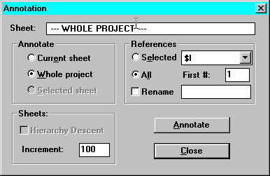
The reference numbers are assigned sequentially in the order that you place symbols on different sheets. As a result, the symbol reference numbers in the multi-sheet schematics can be random. To order the symbol numbers, you may want the symbol reference numbers to correspond to different sheets. For example, symbols on the first sheet may start with U100, and symbols on the second sheet may start with U200.
To renumber project sheets and the associated symbol reference numbers, from the Schematic Capture window proceed as follows:

If you want to move or duplicate a section of a schematic to another sheet, perform the following steps:
The selected schematic block contains all wires internal to the block, that is, between symbols or labels within the selected area. All wires connected to symbols outside the area are not copied to the clipboard.
If a netlist creation error is reported, try removing one sheet at a time from the project until the netlist can be successfully created. Then analyze the last-removed sheet for any possible errors.