This section describes the basic process for performing simulation.
You can invoke the simulator from either the Project Manager or directly from the Schematic Editor. To invoke the simulator (for functional simulation) from the Project Manager, click on the Functional Simulation icon in the Simulation button on the Flow tab.

For a schematic design, you can invoke the simulator (for functional simulation) from the Schematic Editor by clicking on the Simulator toolbar button.

Prior to opening the Simulator, you can attach probes to signals in the Schematic Editor to allow those signals to be automatically loaded into the Simulator Waveform Viewer. Select Mode ![]() Test Points. The SC probes toolbox displays. You can select both input and output test points.
Test Points. The SC probes toolbox displays. You can select both input and output test points.
Figure 9.1 Input Test Points |
Figure 9.2 Output Test Points |
A gray box appears next to the signal name, indicating the placement of the probe. You can add probes at any point during the simulation to add signals to the Waveform Viewer.
Once in the Simulator, you can add signals by selecting the Add Signals toolbar button.

You can create buses by combining any set of signals. Highlight the desired signals and then selecting Signal ![]() Bus
Bus ![]() Combine. This same menu may be obtained by right-mouse-clicking in the signal list area of the Waveform Viewer. To expand or collapse the bus, click on the Bus Expansion toolbar button.
Combine. This same menu may be obtained by right-mouse-clicking in the signal list area of the Waveform Viewer. To expand or collapse the bus, click on the Bus Expansion toolbar button.

You can apply stimulus in a number of various ways.
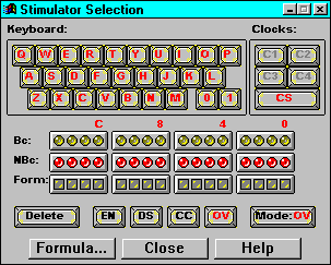
Click the Stimulator Selection toolbar button (below) to access the Stimulator Selection dialog.

Using Stimulator Selection dialog box, you can add stimulus using keyboard keys, formulas, or output signals of an internal software-generated 16- bit binary counter. For more information on these methods, click Help in the Stimulator Selection dialog box.

A second method of applying stimulus is by editing and using waveform test vectors. Test vectors may be edited and/or created using the Waveform ![]() Edit... menu selection. Additionally, test vectors and/or simulation results may be saved by selecting File
Edit... menu selection. Additionally, test vectors and/or simulation results may be saved by selecting File ![]() Save Waveform. These test vector waveforms may then be loaded into the simulator at any time by selecting File
Save Waveform. These test vector waveforms may then be loaded into the simulator at any time by selecting File ![]() Load Waveform.
Load Waveform.
For more information on using and saving waveforms, refer to the online Help at Help ![]() Logic Simulator Help Contents
Logic Simulator Help Contents ![]() Simulator Reference
Simulator Reference ![]() Working with Waveforms.
Working with Waveforms.
A third method of applying stimulus is through a script file macro. Stimulus is entered through commands in the script file (.cmd) and the simulator displays the input and output response in the Waveform Viewer when the script is run.
Foundation 1.5 contains a Macro Editor for creating simulation scripts. See the “Simulation Script Editor” section.
Proper script syntax is documented in the online Help at Help ![]() Logic Simulator Help Contents
Logic Simulator Help Contents ![]() Simulator Reference
Simulator Reference ![]() Simulation Scripts. To run a command script, select File
Simulation Scripts. To run a command script, select File ![]() Run Script File, and choose the appropriate .cmd file. Additionally, you can edit the .cmd file by selecting Tools
Run Script File, and choose the appropriate .cmd file. Additionally, you can edit the .cmd file by selecting Tools ![]() Script Editor.
Script Editor.
Click the Simulator Step icon on the Logic Simulator toolbar to perform a simulation step. The length of the step can be changed in the Simulation Step Value box to the right of the Simulation Step box. (If the Simulator window is not open, select View ![]() Main Toolbar.)
Main Toolbar.)

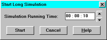
To start a simulation for an extended amount of time, select Options ![]() Start Long Simulation. In the dialog box, enter the desired length of simulation.
Start Long Simulation. In the dialog box, enter the desired length of simulation.

To interrupt the simulation while it is running, click the Stop button in the toolbar.
Save Simulator results by selecting File ![]() Save Simulation State and File
Save Simulation State and File ![]() Save Waveform. Choosing Save Simulation State saves the simulation results and current state of the simulation only. On the other hand, Save Waveforms saves the waveforms in test vector format, allowing you to resimulate the saved waveforms at a later time.
Save Waveform. Choosing Save Simulation State saves the simulation results and current state of the simulation only. On the other hand, Save Waveforms saves the waveforms in test vector format, allowing you to resimulate the saved waveforms at a later time.
For more information about simulator options and features, refer to the online Help by selecting Help ![]() Logic Simulator Help Contents.
Logic Simulator Help Contents.