Options specify how a design is optimized, mapped, placed, routed, and configured. Implementation options are specified in the Options dialog box.
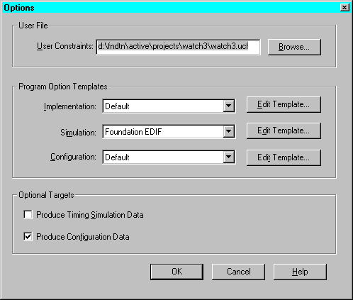
In a Schematic Flow project, select Options on the Implement Design dialog box to access the Options dialog box shown in the following figure.
In an HDL Flow project, select Options on the Synthesis/Implementation dialog box to access the Options dialog box.

User constraints files (.ucf) contain logic placement and timing requirements to control the implementation of your design. In the Options dialog box, you can select the user constraints file to be used during physical implementation of the design. Refer to the “Foundation Constraints” appendix for detailed information on creating .ucf files and on constraint syntax.
Options are grouped into objects called implementation templates, simulation templates, and configuration templates. Each template defines an implementation, simulation, or configuration approach. For example, one implementation style could be Quick Evaluation, while another could be Timing Constraint Driven.
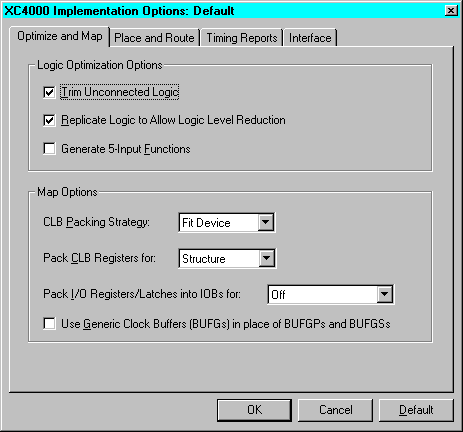
You can have multiple templates in a project. By choosing a template, you are choosing an implementation, simulation, or configuration style. In the Program Option Templates portion of the Options Dialog, select Edit Template for Implementation, Simulation, or Configuration to access the associated template. An example of the Implementation Options dialog box is shown in the following figure. The options shown in each template depends on the target device family. For detailed information on the templates for each device family, refer to the “Implementation Options” chapter of the Design Manager/Flow Engine Reference/User Guide.

Implementation templates control how the software maps, places, routes, and optimizes an FPGA design and how the software fits a CPLD design.
Simulation templates control the creation of netlists in terms of the Xilinx primitive set, which allow you to simulate and back-annotate your design. In back-annotation, physical design data is distributed back to the logic design to perform back-end simulation. You can perform front and back-end simulation on both pre- and post-routed designs. Select a simulation template to use from the Simulation drop-down list.
Configuration templates control the configuration parameters of a device, the startup sequence, and readback capabilities. Select a configuration template to use in this implementation from the Configuration drop-down list.
Configuration options are supported for the FPGA device families only. There are no configuration options for the CPLD families.
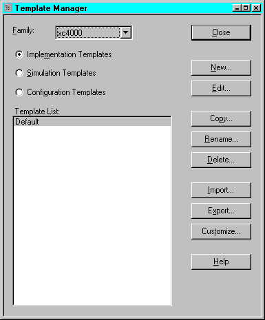
An alternate way to access the templates is through the Template Manager.

If you check Produce Timing Simulation Data on the Implementation Options dialog box, the Flow Engine produces timing simulation data files. For FPGAs, the files are produced after the design is placed and routed and before it is configured. The data files are produced after the design is fitted for CPLDs.You can use these files to simulate the design with a supported third party simulation tool.
If you check Produce Configuration Data, the Flow Engine produces configuration data files after design implementation. This data can be used to program a device.