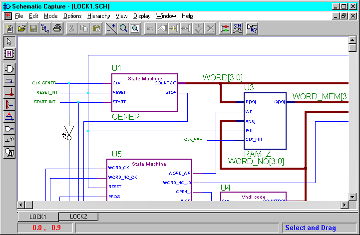
This section describes various tips for creating schematic designs.
Symbols are color-coded to represent their type.
These color codes are the default values. If you wish to change the defaults, select View ![]() Preferences
Preferences ![]() Colors from Schematic Capture.
Colors from Schematic Capture.
Only use the Hierarchy Connector when specifying pins for a schematic macro. Never use hierarchy connectors on top-level schematic sheets.

Xilinx schematics require that you use input and output buffers between input and output ports. The following figures illustrate incorrect and correct input and output port design.
Figure 4.3 Incorrect Port Design (Without Buffers) |
Figure 4.4 Correct Port Design (With Buffers) |
Tabs on a schematic sheet facilitate navigation between schematic sheets. The following example shows the tabs that display after opening the schematics for the “lock” project.

Note the LOCK1 and LOCK2 tabs in the lower left corner of the figure. Clicking on the LOCK2 tab navigates to the LOCK2 schematic sheet. For every new schematic sheet added to the design, a new tab displays.
In addition, if you use Hierarchy ![]() Push to display the schematic for a component or macro, a new tab also displays in the lower left corner.
Push to display the schematic for a component or macro, a new tab also displays in the lower left corner.
In Foundation 1.5, you can simulate a macro in a schematic design: