LogiBLOX can be started from the Project Manager window using Tools ![]() Design Entry
Design Entry ![]() LogiBLOX module generator. LogiBLOX can also be started within Schematic Capture by selecting Options
LogiBLOX module generator. LogiBLOX can also be started within Schematic Capture by selecting Options ![]() LogiBLOX or in the HDL Editor by selecting Synthesis
LogiBLOX or in the HDL Editor by selecting Synthesis ![]() LogiBLOX. The LogiBLOX Module Selector dialog box then opens. See the “LogiBlox Module Selector - Accumulators” figure for an example.
LogiBLOX. The LogiBLOX Module Selector dialog box then opens. See the “LogiBlox Module Selector - Accumulators” figure for an example.
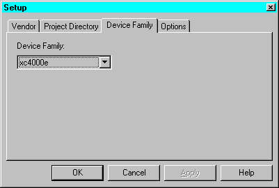
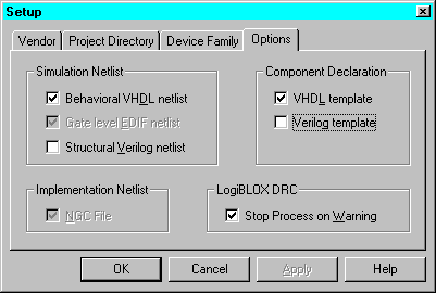
The first time you access LogiBLOX, a Setup dialog appears. Or, you can click Setup on the LogiBLOX Module Selector dialog box to access the Setup dialog box.
Use the Device Family tab (shown below) to select a Device Family.

You can instantiate a LogiBLOX module in VHDL or Verilog code. Use the Options tab to select appropriate Simulation Netlist and Component Declaration template. For VHDL, select VHDL template and Behavioral VHDL netlist (shown below). For Verilog, select Verilog template and Structural Verilog netlist.

You can use LogiBLOX components in schematics and HDL designs for FPGAs and CPLDs. Once you are in the LogiBLOX GUI, you can customize standard modules and process them for insertion into your design.
Once a LogiBLOX module is created, do not change parameters for the module on the schematic. Any changes to the module parameters must be made through the LogiBLOX GUI and a new module created.
You can also import an existing LogiBLOX module from another directory or project into the current project library by selecting Options ![]() Import LogiBLOX from the Schematic Capture window and choosing the .MOD file of the module you want to import. For details, see the “Importing Existing LogiBLOX Modules” section of the “Design Methodologies - Schematic Flow” chapter.
Import LogiBLOX from the Schematic Capture window and choosing the .MOD file of the module you want to import. For details, see the “Importing Existing LogiBLOX Modules” section of the “Design Methodologies - Schematic Flow” chapter.
Figure 8.1 LogiBlox Module Selector - Accumulators |